

This instructable introduces a spirometer with CO2 analysis capabilities, which measures the volume and speed of air inhalation and exhalation. In addition to standard spirometry, it includes capnographic features to gauge CO2 concentration in respiratory gases. The spirometer records expelled CO2 (up to 50,000 ppm) and exhale pressure in kilopascals using built-in sensors. These data fuel calculations for the user’s instantaneous breathing rate, Forced Vital Capacity (FVC), and overall breathing rate. An LED display provides real-time feedback, while cloud storage facilitates data streaming via a connected microprocessor.

This spirometer uses Arduino for software (IDE and code/sketch) and hardware (microprocessor and board). To download the Arduino IDE, please refer to this link.
The spirometer incorporates 3D printed components. Most commercially available 3D printers support this instructable. Prior to starting, confirm that your 3D printer can open and process .stl files.
Bill of Materials (Unit costs revised July 2020)
- Arduino Uno Rev 3 $22.00
- StripBoard, 50x80mm $3.16
- Comes with pins
- Board Mount Pressure Sensor $17.40
- Airline Tubing $6.99
- 1″ Vinyl Tubing $23.63
- UART Infrared CO2 Sensor (0-50,000 ppm) $89.00
- Comes with wires and adapter
- OLED Display $7.95
- Disposable Cardboard Mouthpieces $26.99
- 3 mm diameter, 20 mm long Hex screws $1.40
- Unit price is $0.70, but we need 4 screws, thus 2 packs
- TOTAL $198.52
Furthermore, you will require 2 x 3 Dupont jumper wire housing, basic workbench tools, zip ties, soldering materials, and your 3D printer software/filament to successfully finish this project.
Step 1: IDE and Sketch
We initiate this instructable by delving into the spirometer’s software and its implementation. To complete this step, a computer and a stable internet connection are necessary.
Section 1A:
First we need to download the program that runs the spirometer. Assuming you already have the Arduino IDE installed, download the sketch from the old.oval.bio GitHub repository or download the file Spirometer.ino from the open source Google Drive folder. To properly upload or make edits to the sketch through the Arduino IDE, ensure you enable OLED screen support and select the correct boards/ports. The following details the process to check these two items and change their respective settings.
Section 1B:
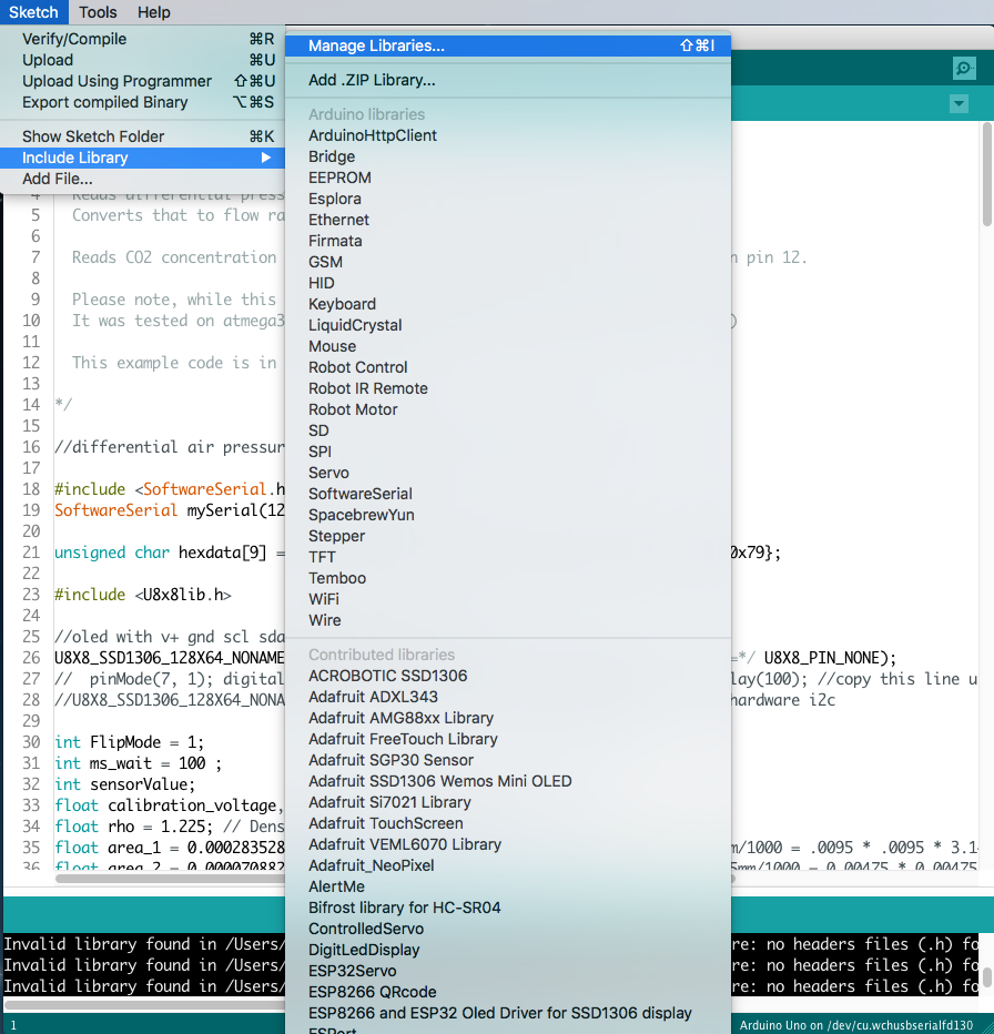
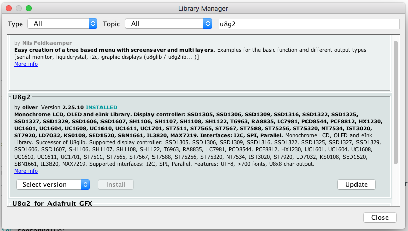
To activate OLED screen support (or confirm its activation), go to the menu bar and select “Sketch” > “Include Library” > “Manage Libraries” (Figure 1B.1). In the Library Manager, search for “U8g2.” If OLED screen support is not enabled, locate the “Install” button (Figure 1B.2) and proceed to install the latest version. If an “Update” button is present, ensure you update the U8g2 library installation (Figure 1B.3). The window will show whether the library is installed and fully updated (Figure 1B.4). Once you install and update the U8g2 library, OLED screen support becomes active.


Configuring Boards and Ports: Ensuring Proper Arduino Board and Port Selection
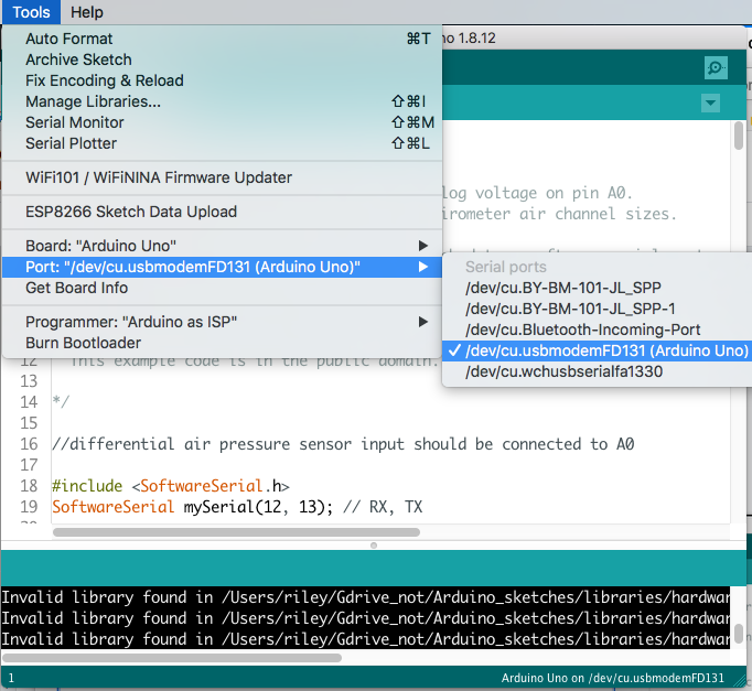
Moreover, confirm the selection of the appropriate boards and ports. Connect the USB cable to both the Arduino Board and the computer (Figure 1B.5). If the program has never been uploaded to the Arduino board, the screen will display blank. In case of a previous upload, it will resemble Figure 1B.5. Subsequently, access the menu bar and proceed to “Tools” > “Boards,” choosing the relevant Arduino type, such as Arduino Uno (Figure 1B.6). Then, within the “Tools” menu, navigate to “Port” and verify that the selected Arduino type aligns with the one chosen earlier (Figure 1B.7).


Section 1C:
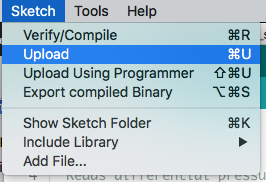
After composing the preferred sketch in the IDE, proceed to upload it to the Arduino Board. Before initiating the upload, refer to Section 1B. Repeat this section (and Section 1B) whenever there is an update to the sketch.
Step 2: Modify the Sketch
Section 2A:
If you have no plans to modify the sketch, you can proceed to Step 3. Modifying the sketch involves adjustments like changing input pin locations, altering LED screen displays, adding or modifying calculations performed by the spirometer, etc.
Examining the downloaded code’s sketch reveals the basis for the calculations displayed on the LED screen. As mentioned earlier in the instructable, the user provides the primary input data sources, including CO2 expelled in parts per million and pressure in kilopascals measured by the pressure sensor. With these variables, the spirometer calculates various breathing characteristics.
Determining CO2 Readings: Conversion Process and Sensor Calibration
Before computing these values, it’s essential to understand how these two variables are determined. The sensor directly measures CO2 readings, as observed in line 209. The high and low concentrations are summed, with the high concentration multiplied by 256 to convert bytes of data to the actual numerical reading. This determination is based on the CO2 sensor’s instruction manual listed in the BOM. If your sensor differs, consult the manual to determine how to obtain the parts per million of CO2 expended by the device user.
Section 2B:
The following bullet points outline the calculation process for each value in the provided code. If you wish to alter the spirometer’s output units, such as changing kilopascals to Standard atmospheres, or adjust the dimensions of the spirometer tubing, please carefully review this section.
- We calculate the breathing pressure in kilopascals based on the specifications of our pressure sensor. Additionally, we consider the voltage measured by the pressure sensor and the offset voltage. These two variables, which are not constant, determine the pressure. The formula used is given below:

Figure 2B.1
where P is the outputted pressure in kilopascals, and Vmeasured is the voltage measured by the sensor in Volts, and Voffset is the voltage by which the measured voltage is offset, in order to determine the pressure. Both Vmeasured and Voffset are determined by multiplying the differential pressure, Pdifferential and the initial differential pressure, P0, by the ratio 5/1023 because when reading an analog voltage from an input pin, the value is returned as a number from 0 to 1023; for a range of 0 V to 5 V. Essentially, the ratio converts the number read by the sensor into an actual voltage.
Pressure Calculation Formula: Adjusting for Sensor Characteristics
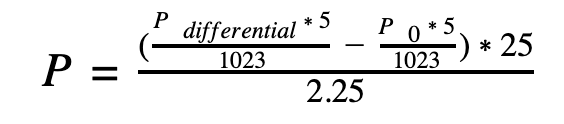
After subtracting Vmeasured by Voffset, their difference is multiplied by the ratio of rangegauge/Vrange, where rangegauge is a constant 25 kpa, and represents the range of the pressure sensor. This value will change based on the make and model of each pressure sensor. Vrange is a constant 2.25 V and represents the voltage range of the pressure sensor. The range is 2.25 V because its range for negative pressure is 0.25 V to 2.5 V and range for positive pressure is 2.5 V to 4.75 V. Furthermore, this value may vary depending on the pressure sensor used. Thus, the formula for pressure in kilopascals is calculated based on the constants from the pressure sensor used:
- The instantaneous rate of the users breathing is calculated via the formula below:

where air is the density of ϱair in kg/m3 (1.225).
Based on the equation above it is clear that volume flow is mass flow over ϱ. We can continue to rewrite the equation above by expanding the equation for mass flow rate and considering unit conversions:

Figure 2B.4
Expressed as P, the pressure in pascals is calculated using the density of air (ϱair) in kg/m³ and the areas of the smaller (A2) and larger (A1) tubes through which the user breathes. These holes are created later in the instructable during the 3D printing of the mouthpiece in Step 4. While it is recommended to adhere to the provided measurements in the 3D prints, if different dimensions are used, determine the radius of each tube in meters, square the radii, and multiply by π. Adjust the values of areas 2 and 1 (small and large, respectively) in lines 36 and 35 in the code accordingly.
Given that all the values for the mass flow rate, including pressure, air density, and areas, are already known, calculating the mass flow rate and, consequently, the instantaneous rate of breathing (in liters per second) is straightforward.
- The final value calculated in the code is the Forced Vital Capacity (FVC), or the total amount of air (in liters) expelled per singular breath.
Calculating FVC Logic: Volume Measurement During Breathing Cycles
The logic behind calculating FVC is relatively simple. When the user is in between breaths, their instantaneous rate of breathing is zero liters per second since they are not expending air. When the user is breathing, their rate of breathing is greater than zero. Thus, in the sketch, whenever the instantaneous rate of breathing (calculated above), is greater than 0.1 liters per second (used instead of 0.0 to mitigate error), the microprocessor will continue adding volume until the rate of breathing goes below 0.1 which is when breathing stops. This value is stored, and the subsequent breath’s volume gets measured using the same method.
Section 2C:
There are even more modifications that you as a user could make to this sketch, specifically, what the LED screen displays, and the update frequency.
To modify the specific content displayed or alter the text’s positioning on the screen, refer to lines 77-84. Adjust the (x, y) coordinates by modifying the inputs in the setCursor() function, and alter the text by changing the inputs in the print() function. Make sure to keep the quotes inside the print() function, and also make sure the text printed on the screen is not too long. That will result in the text “going off the screen,” and not being visible on the LED.
Customizing Update Frequency: Adjusting Values for Optimal Data Processing
To modify the update frequency, reference lines 99-116. Each if statement contains a value for the variable current_tenth, representing the tenth of a second at which a value is updated. To customize when these values are updated, simply change the value of current_tenth to any value between 0 and 9, inclusive. However, to prevent overloading the microprocessor with data, it’s advisable to avoid having values change too frequently or having too many values changing simultaneously or at similar times.
Step 3: Build the Board
Now we will transition to assembling the hardware of the spirometer.
Section 3A:
Start with your blank shield as shown below (Figure 3A.1).

Soldering the Pressure Sensor: Ensuring Proper Mounting and Connectivity
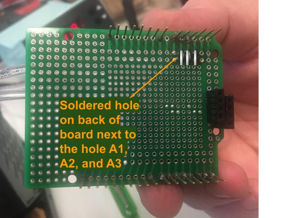
Proceed by soldering the pressure sensor on one edge of the board. Ensure that one side of the pressure sensor’s mounts lies on the holes adjacent to A0 to A3 (the analog input holes), respectively. Additionally, make sure that the three adjacent mounts from A1 to A3 are soldered to the board (but not the fourth at A0), and that two of the mounts on the other side are soldered for support (Figure 3A.2). On the bottom side of the board, solder A1, A2, and A3 to the adjacent hole where one of the mounts of the pressure sensor is located, in order to connect the pressure sensor to the trace (Figure 3A.3), ensuring electronic connectivity for the pressure sensor.’
Ensuring Tubing Attachment Clearance: Preventing Contact Between Pressure Sensor Nipples and Board
For optimal results in subsequent steps, make sure that neither of the nipples of the pressure sensor comes into direct contact with the board, as tubing will be attached to the nipples in future steps. This is particularly crucial for the nipple closest to the board, where there should be a visible gap of a few millimeters between the nipple and the board. While this might be a bit challenging, it is acceptable to proactively attach the airline tubing (as outlined in Section 3B) to the nipple closest to the board before soldering.

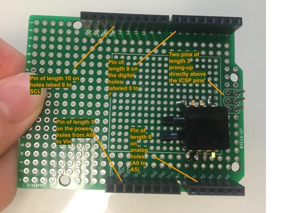
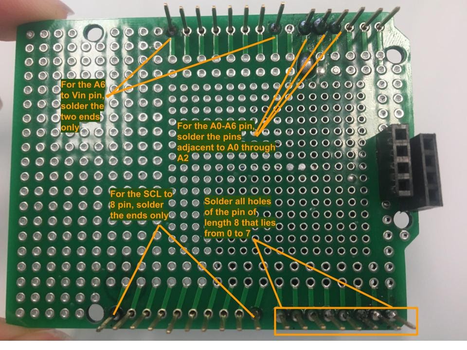
On the board, arrange stacking headers along the outer perimeter. Specifically, place a total of six stacking pins on the board. The first four pins will be oriented prongs-down (relative to the top of the board): a stacking pin of length 8 on the digital holes labeled 0 to 7, a stacking pin of length 10 on holes labeled 8 to SCL, a stacking pin of length 6 on analog holes (A0 to A5), and a stacking pin of length 8 on the power holes from A6 to Vin. Additionally, position two stacking pins prongs-up, both of length 3, directly above the ICSP pins on the Arduino Uno board—which should be distinctly labeled or boxed on the shield (Figures 3A.4 and 3A.5).

Next, take the LED and put a (normal) pin of length 4 underneath the LED (Figure 3A.6).

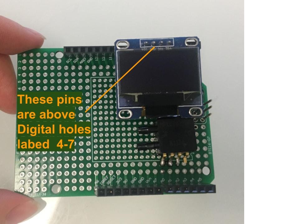
Attach the appended pins on the LED screen to holes above Digital holes 4 to 7 (Figure 3A.7).
Section 3B:
Next, solder all the loose stacking pins in place. It is not necessary to solder each hole of each pin in place.
Solder the specified pins from the bottom of the board. For the pin of length six (extending from A0 to A5), it is only necessary to solder the pins adjacent to A1 through A3. These are the same holes that should be next to the soldering of the 3 prongs of the pressure sensor (on the other side of the board, however). For the pin of length 8, spanning from A6 to Vin, solder only the two ends—the holes adjacent to A6 and Vin. The same applies to the pin of length 10 located next to holes SCL to 8—only solder the ends (SCL and 8). Solder all the holes of the pin of length 8 that spans from 0 to 7. Refer to the illustrative example in the figure below (Figure 3B.1).
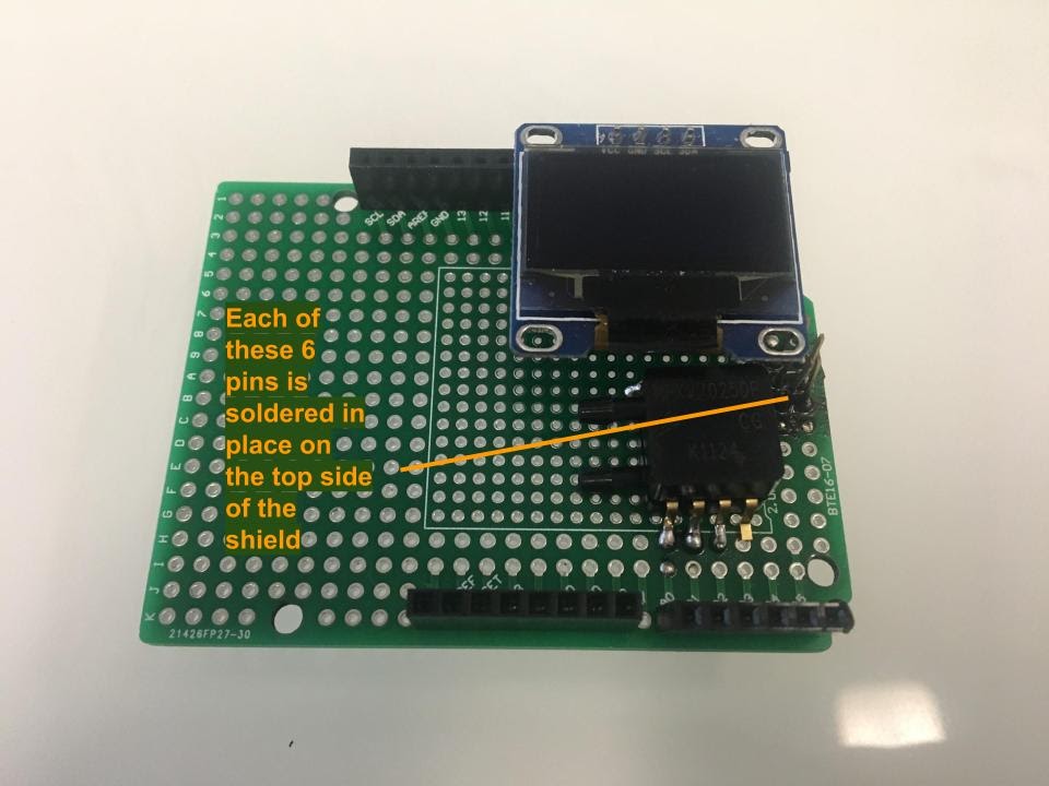
Solder the remaining pins, two of length 3 each, directly above the ICSP pins on the Arduino Uno board. Solder all six holes for these two pins in place from the top of the board (Figure 3B.2). If needed, you can remove and replace the LED display, especially if it is positioned on top of the pins, making it challenging to solder.
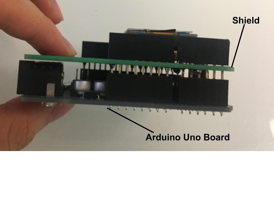
Next, stack the shield on top of the Arduino Uno board. All the pins should align with the holes/pins from the Arduino (ie A0 to A6 pin on the shield goes over the associated A0 to A6 holes on the Arduino, etc.) (Figures 3B.3 and 3B.4).

Tubing Preparation: Fitting Airline Tubes to Pressure Sensor Nipples
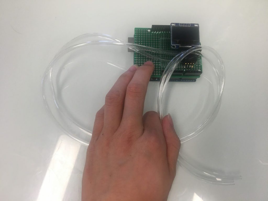
Cut 2 pieces of airline tubing, each approximately 2 ft in length with scissors. Take the tubes and fit one through each nipple of the pressure sensor (Figure 3B.5). If you find it difficult to place the tube into the lower nipple because of interference with the board, consider resoldering the pressure sensor so that it fits higher on the board, which will allow for the airline tubing to attach to the nipple of the sensor (Figure 3B.6).

Section 3C:
Place the board to the side for now.
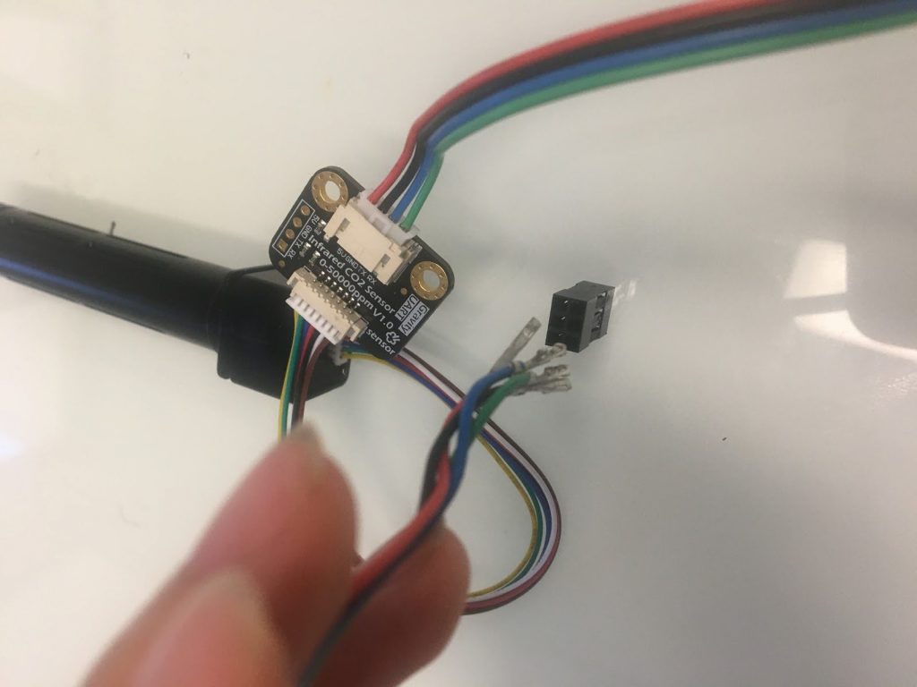
Focusing now on the CO2 sensor, connect the adapter (that comes with the CO2 sensor) to the CO2 sensor as shown (Figure 3C.1). Ensure that the connection occurs on the correct side of the adapter.

Next, attach Dupont jumper wires to the other side of the adapter (Figure 3C.2).

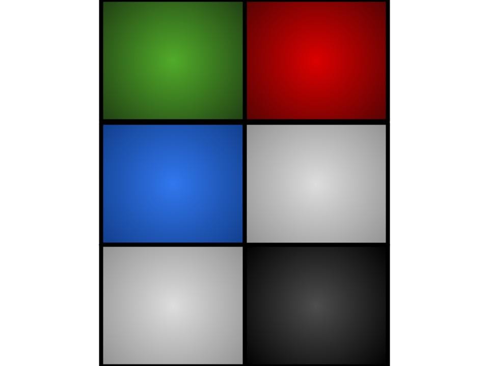
Attach the end of the Dupont wires to the wire housing (Figure 3C.3). Make sure the associated wires connect to their associated port in the 2 x 3 wire housing. The diagram below represents the arrangement to put each colored wire in (gray represents an empty port) (Figure 3C.4). Also note that these ports are associated with the sketch that comes with instructable. Any modifications to the input pins on the sketch might require you to put wires into different ports.
Wiring Assembly: Inserting Wire Housing and Verifying Connection
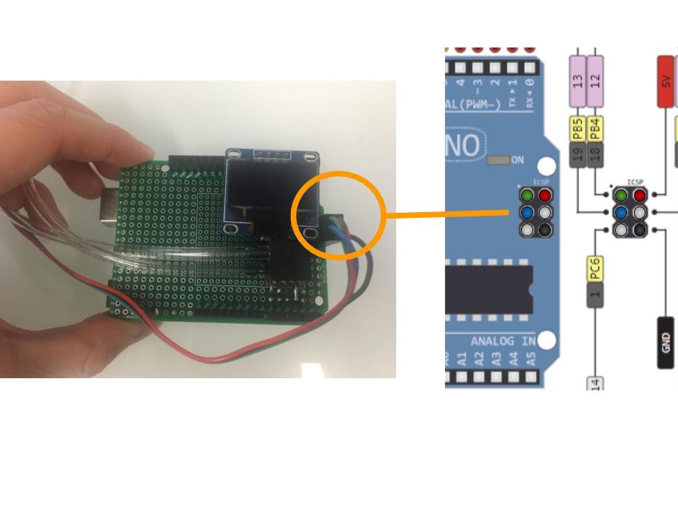
Following that, insert the wire housing into their respective male pins on the Arduino board (Figure 3C.5). Again, verify that you place the correct pins in their corresponding housing ports according to the schematic (Figure 3C.6). Ensure the alignment of the jumper box on the Arduino matches these figures. Adjusting the OLED display slightly may be necessary to fit the pins into the ports. It might also be easier to remove the OLED, connect the wire housing male and female parts, and then reposition the OLED display in its original position.
Step 4: 3D Printing
This next step will detail the printing process for the 3D parts needed to build the spirometer.
Section 4A:
We will first print the 3D files using a 3D printer. To access the files needed to print the files click the link here for the open source Google Drive folder. The following are the .stl files to be printed:
- CO2_holder.stl (this part needs to be printed TWICE)
- inner_cap.stl
- removable_mouthpiece.stl
- spirometer_body.stl
- vinyl_plug.stl
This equates to a total of 6 parts to be printed.
Refer to your 3D printer manual and FAQs for instructions on the setup, printing, and clean up for your specific make and model.
Optimizing 3D Printing: Adjusting Orientations, Dimensions, and Clearing Filament
Some of the parts (particularly the CO2 holders) are more compatible with certain 3D printers when rotated at different orientations. You might have to adjust the orientation of the files to whatever is most compatible with your type of printer.
Additionally, because of differences in error in every 3D printer, it might be necessary to adjust some of the dimensions of each part and test several iterations of the design if some of the parts don’t fit into others.
All parts, especially the CO2 holder, which is divided into two parts, were designed with minimal scaffolding in mind. However, depending on your printer and printing orientation, it may be necessary to ensure that all parts and holes are free of any filament or scaffolding before proceeding.
Section 4B:
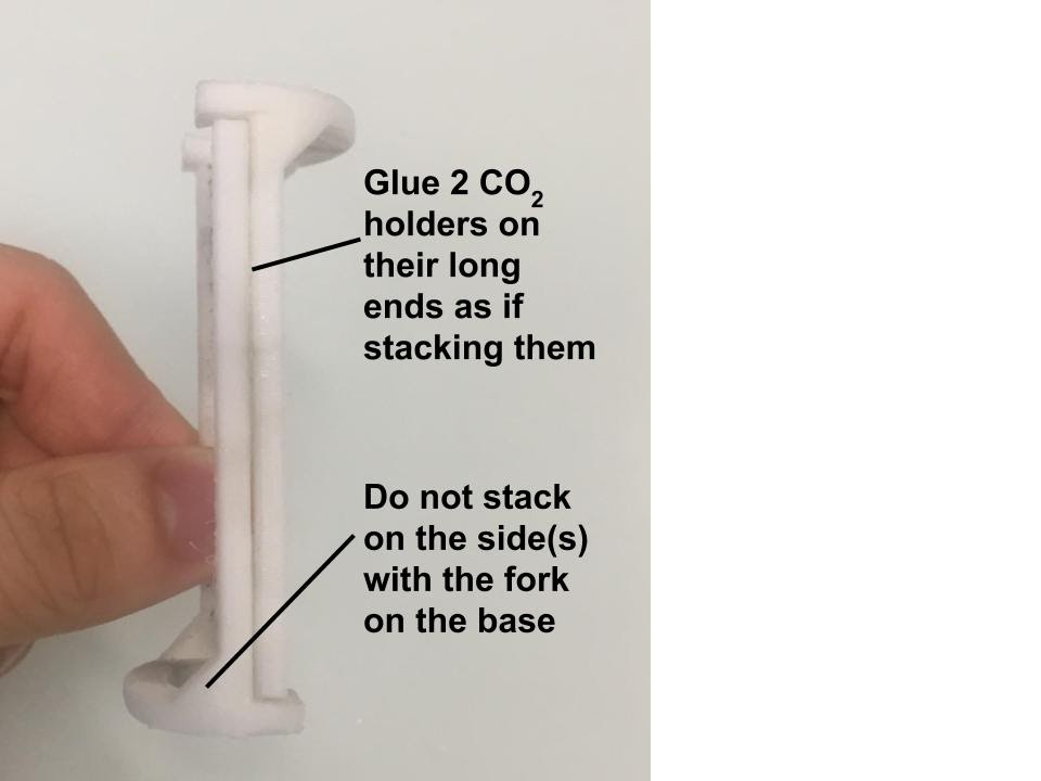
Following that, adhere the CO2 holders together using their non-forked, long ends, ensuring that both parts stack on top of one another (Figure 4B.1). While any strong glue will work, we recommend using super glue for this step and all subsequent steps involving gluing.
Step 5: Assembling the Spirometer
The home stretch of this spirometer building involves connecting all the parts from previous steps together.
Section 5A:
Initially, take the CO2 holder crafted and glued in Step 4 and slide it onto the CO2 sensor (Figure 5A.1). Ensure you slide the holder onto the sensor from the bottom and not ‘pop it in,’ as the latter might lead to the holder breaking under external pressure.
Airline Tubing Installation: Aligning and Securing Tubes in Spirometer Body
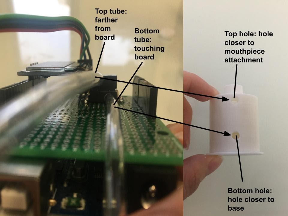
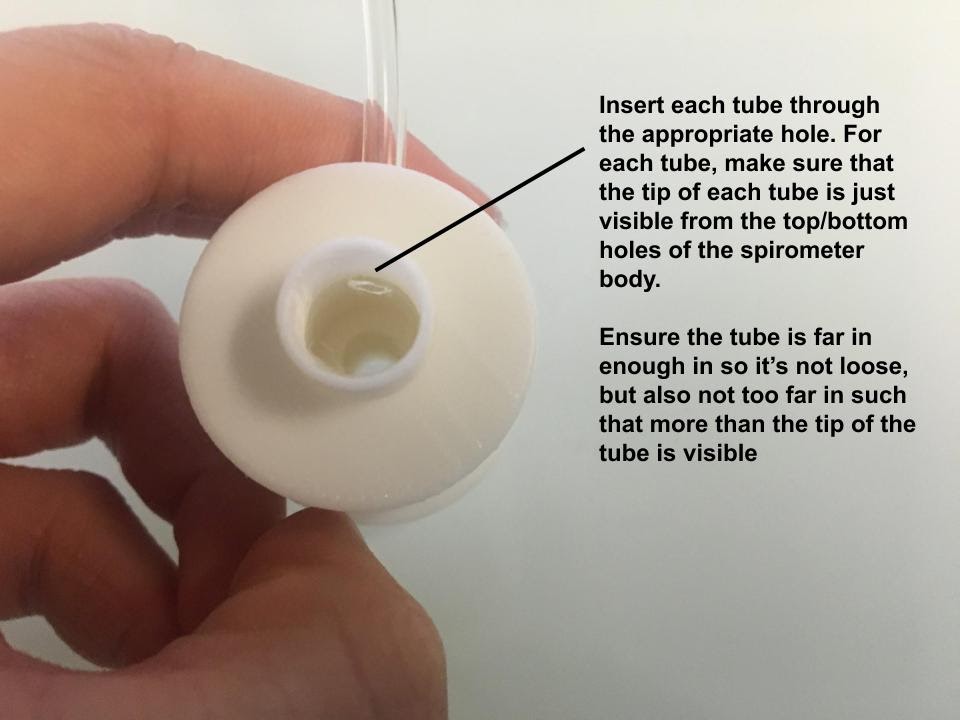
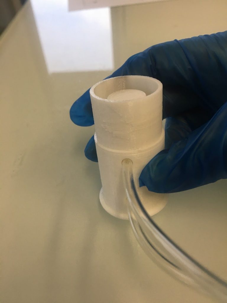
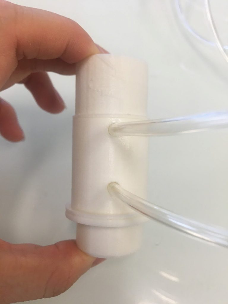
Set the CO2 sensor to the side. Stick in the airline tubing (attached in Step 3) into the two holes of the 3D printed spirometer body. Ensure that the correct airline tube goes into the correct hole on the body. The “top” tube on the pressure sensor should align with the “top” hole on the spirometer, and the “bottom” tube with the “bottom” hole (Figure 5A.2). When inserting the tubing, look through the top of the hole to ensure that each tube just gets through the hole: the tubes should not extend past the opening to a significant degree nor be too loose in the hole (Figure 5A.3). Super glue these tubes in place (Figure 5A.4).

Set the spirometer body to the side. Take the 3D printed inner cap and add a few dabs of superglue to the inner edge. Then stick the cap onto the top of the 3D printed removable mouthpiece (Figures 5A.5 and 5A.6). If the parts don’t fit, consider adjusting the dimensions of these parts and reprinting.


Afterward, connect the bottom of the removable mouthpiece to the top of the 3D printed spirometer body (Figure 5A.7). Do not attach with superglue, as the mouthpiece is designed to be removed for washing between uses. This removable mouthpiece, designed for convenience, is dishwasher and soap-friendly (if using ABS filament). If the parts do not fit, consider adjusting their dimensions and reprinting.
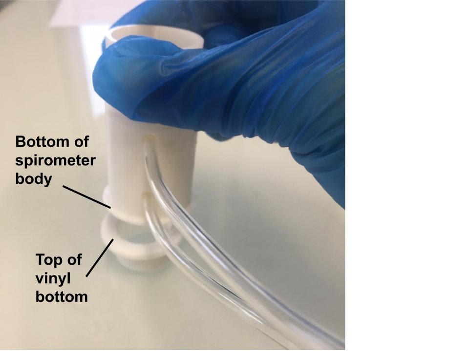
Next, super glue the bottom of the spirometer body to the top of the 3D printed vinyl bottom (Figures 5A.8 and 5A.9). Once more, if the parts don’t fit, consider adjusting the dimensions of these parts and reprinting.
Preparing Tubing for CO2 Sensor Placement: Cutting a 9-Inch Length
Next, use a cutting tool (such as a hacksaw, table saw, or a simple carpet knife) to cut a 9-inch length of vinyl tubing (Figure 5A.10). This is the space where you will position the CO2 sensor and holder combination. We decided to cut 9 inches to accommodate the current contents within the tube and allow extra room in case future iterations of the spirometer include additional components in the vinyl tubing.

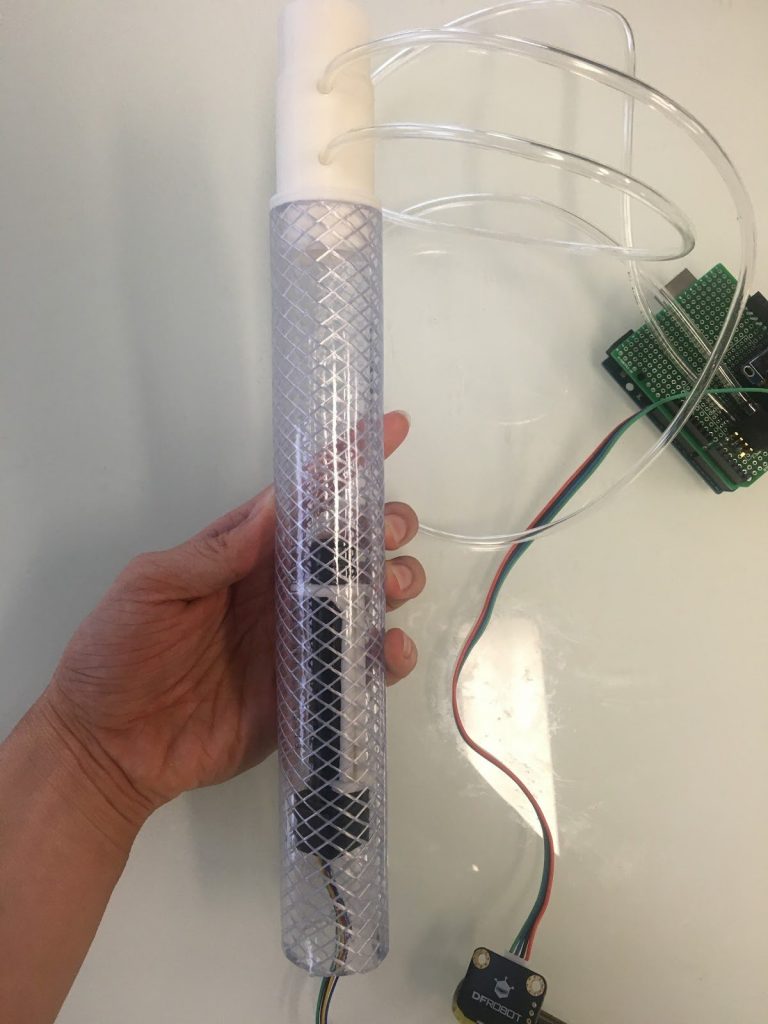
Finally, connect the bottom of the vinyl bottom 3D printed part with one side of the vinyl tubing. On the other side, insert the CO2 sensor (Figure 5A.11). Ensure that you do not insert the CO2 sensor too far into the tube, as this may make it difficult to remove in the future.
Note that in between uses of individuals, use a new cardboard mouthpiece. Insert these mouthpieces by attaching to the 3D printed removable mouthpiece part. In between several uses, remove and wash the removable mouthpiece.
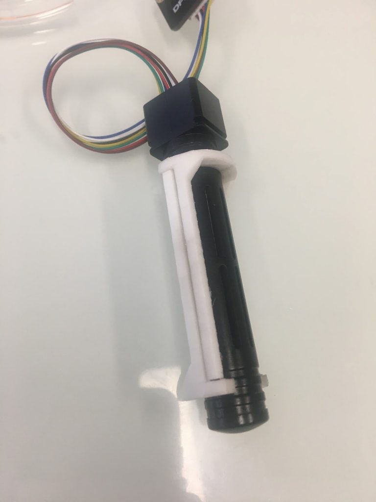
Your product should now look like this (Figure 5A.12):

Step 6: How to use the Spirometer
This step explains how to use the spirometer after assembly. To verify the proper completion of all assembly steps and ensure the functionality of the spirometer, follow the instructions in this step.
Section 6A:
To begin, connect the spirometer to the USB port of the Arduino board, and plug the other end of the cord into a computer (Figure 6A.1). Allow one minute for the CO2 sensor and Arduino board to warm up. Before proceeding, ensure that you have successfully uploaded the most updated sketch to the Arduino board, as detailed in Section 1B and 1C.

Enhancing Data Management: Printing and Saving on Computer for Analysis
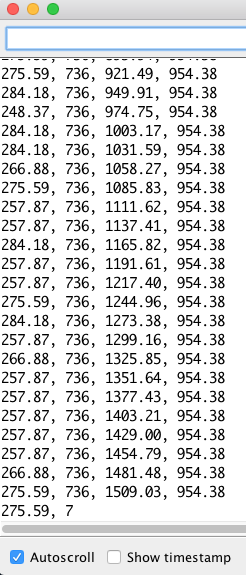
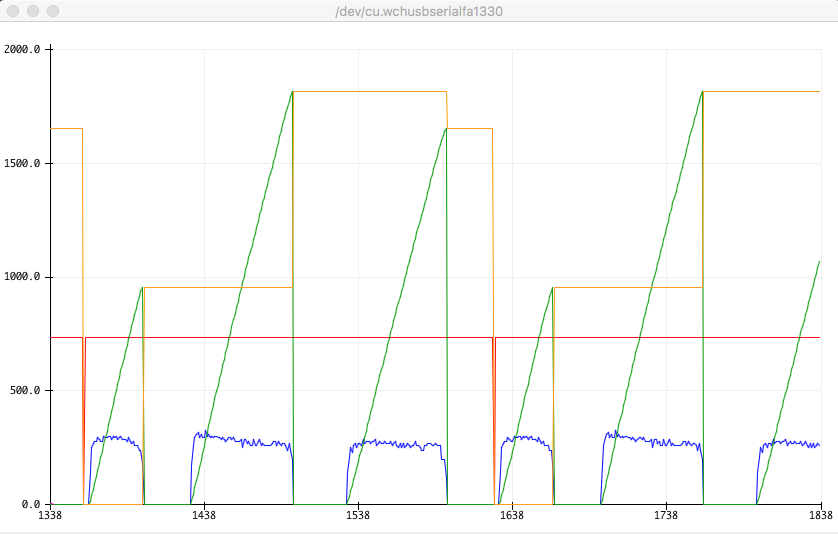
Preferably, print and save data on the computer rather than relying solely on real-time display on the OLED screen. To print values on the screen, open the Arduino IDE, navigate to the menu bar, and select “Tools” > “Serial Monitor” for text format display (Figure 6A.2). For a graphical format, choose “Tools” > “Serial Plotter.” To ensure these steps work correctly, follow and execute the procedures outlined in Section 1B (Figure 6A.3). You can copy and paste these text values into Excel or a .CSV file, or capture screenshots of the serial plotter. Examples of the Serial Monitor (Figure 6A.4) and Serial Plotter (Figure 6A.5) are also provided below.


Usage and Data Monitoring: Breathing into the Spirometer for Real-Time Measurements
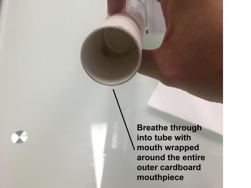
After one minute, breathe into the tube of the spirometer (Figure 6A.6). As the user breathes into the tube, the OLED screen displays real-time values for each measured variable, and the terminal of the serial monitor or serial plotter prints a continuous set of data if enabled earlier. Make sure to attach a new cardboard mouthpiece to the end of the tube before breathing.
Each row of printed values represents one set of data, and an additional row is added every second. The values printed on the table from left to right are instantaneous rate (L/sec), CO2 concentration in ppm, volume of current breath (L), and volume of previous breath (L).
After attaining and saving the desired data, unplug the USB cord from the Arduino and computer. Also, remember to remove the cardboard tube.
Section 6B:
In order to confirm that the values measured by the spirometer are accurate, there are a couple tests that will confirm its accuracy.
If the following tests return the correct values, we can assume that the spirometer was built correctly, the implemented changes are accurate, and the CO2 sensor is functional:
- When testing the CO2 concentration outside, the measured amount on the LED screen should show approximately 400 ppm.
- When testing the CO2 concentration inside, the measured amount on the LED screen should show anywhere in or around the range of 400 – 1,000 ppm.
- When blowing into or in the direction of the tube, the rate of breathing, measured CO2 concentration, and volumes of current and previous breaths, should all increase on the LED screen.
Section 6C:
Here’s a video demonstrating how to use the spirometer. It provides insight on set-up, usage, and post-usage.
Step 7: 3D Printing and Assembling Part 2
This step is an optional (but highly recommended) step to make additional 3D printed parts to hold the spirometer together. Completing this step will make using and moving the spirometer around much easier.
Section 7A:
We will first print the 3D files using a 3D printer. To access the files needed to print the files click the link here for the open source Google Drive folder. The following are the .stl files to be printed:
- Ring.stl (this part needs to be printed TWICE)
- TopBox.stl
- BottomBox.stl
This equates to a total of 4 parts to be printed.
The following are similar reminders as listed in Step 4:
Refer to your 3D printer manual and FAQs for instructions on the setup, printing, and clean up for your specific make and model.
Fine-Tuning 3D Printing: Orientation, Dimensional Adjustments, and Scaffolding Clearance
Some of the parts are more compatible with certain 3D printers when rotated at different orientations. You might have to adjust the orientation of the files to whatever is most compatible with your type of printer.
Additionally, because of differences in error in every 3D printer, it might be necessary to adjust some of the dimensions of each part and test several iterations of the design if some of the parts don’t fit into others.
We designed all parts with minimal scaffolding in mind. Depending on your printer and printing orientation, you may need to clear any filament or scaffolding from all parts and holes before proceeding.
Section 7B:
After printing all parts, configure the wires and adapter above the board in a manner similar to the illustration below (Figure 7B.1). Everything should be as compact as possible.

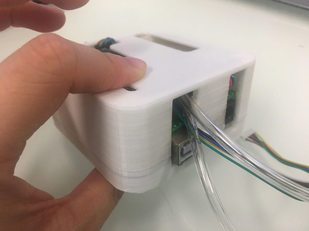
Next place the TopBox part on the top of the board and wires/adapter (Figure 7B.2 and 7B.3). Ensure proper alignment of the 3D printed part so that the OLED screen is visible, and all the ports on the side align correctly.

Assembly: Fitting the BottomBox Part and Ensuring a Snug Fit

Place the BottomBox part on the bottom of the board (Figure 7B.4). It should attach with the TopBox part and all the wires along with the adapter and board should fit snugly within the box. If not, it might be helpful to rearrange these items within the box. Keep in mind that error on each 3D printer might mean that the items in the box might not fit, so resizing the box might be necessary as well.
Next add a total of four 3 mm Hex screws (20 mm length), one to each corner, of the BottomBox part to connect to the TopBox part (Figure 7B.5). If the holes on the box are too small due to errors in 3D printing, drill the holes with a 7/64 inch drill tip, or adjust the size on your 3D printing software and reprint.
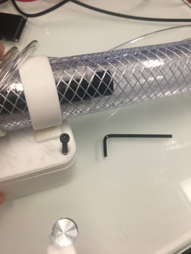
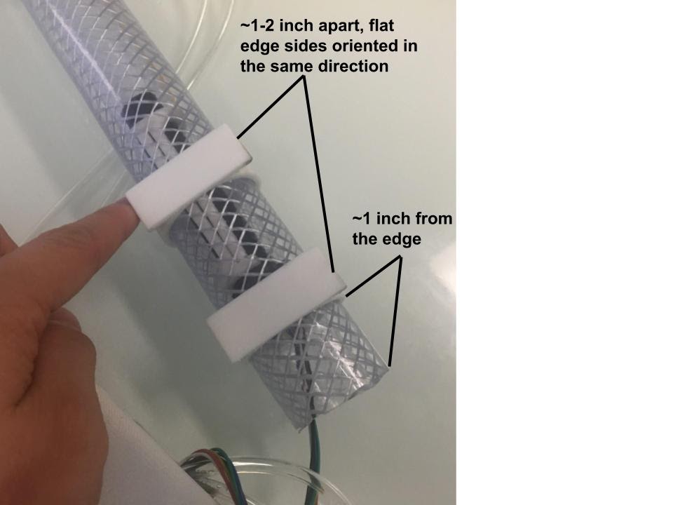
Next, slide the two Ring parts onto the tube. Ensure that the flat edges are oriented in the same direction. They should be about 1-2 inches apart, and the ring closest to the end of the tube should be about 1 inch away from the end (Figure 7B.6).
Next, glue the BottomBox to the flat edges on the rings (Figure 7B.7).

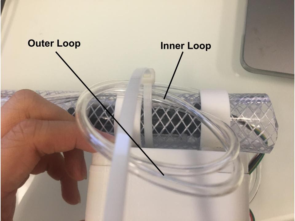
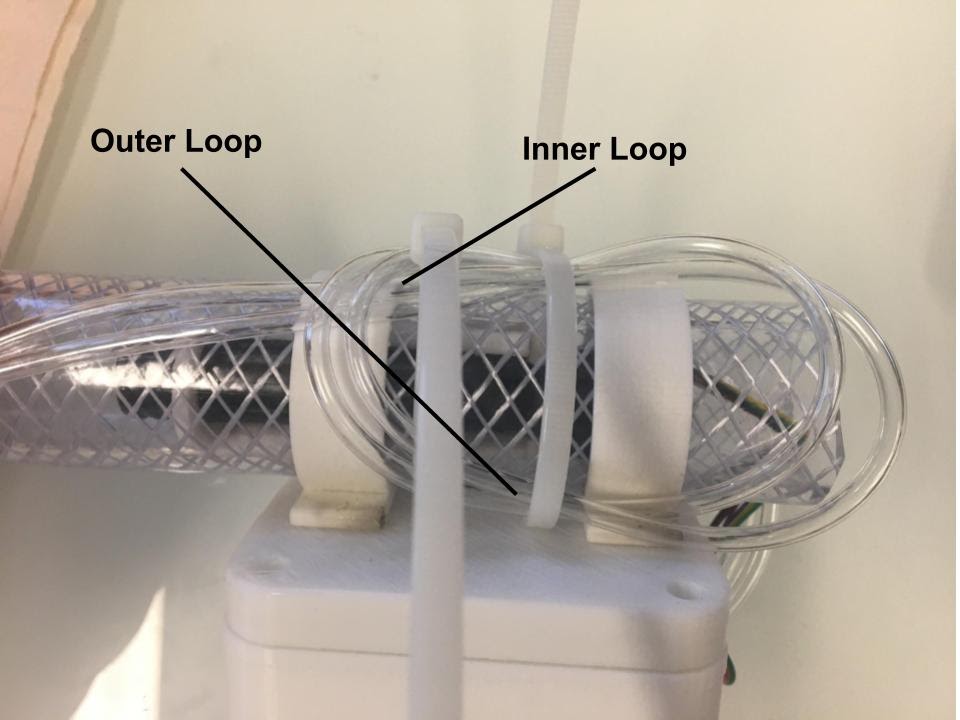
Finally, secure the airline tubes by using zip ties against the vinyl tubing positioned behind and under the 3D printed box. Twist the airline tubing once and place two zip ties on the tubing behind the 3D printed box—one on the inner loop, the part where the loop of the tubing “intersects itself” (Figure 7B.8), and then another one on the inner loop (Figure 7B.9). Ensure that applying the zip ties and looping the tubing does not impede airflow through the tubes. To confirm that the zip ties are not restricting air, retest the spirometer using the instructions in Step 6—expect to observe consistent results.
Cut the excess zip tie (Figure 7B.10). The final product should look like the image below (Figure 7B.11).


Appendix:
Performing a few steps in a different order than presented in the instructable can be beneficial.
- Place the nipples on the pressure sensor before soldering the pressure sensor onto the board. Add the OLED screen as the last component to the board. First solder on all parts and attach all wires on
Due to minor errors during the creation of this instructable, there might be slight discrepancies between some images and the preceding steps. Nonetheless, ensure precise soldering onto the correct pins/areas of the board. When uncertain, adhere to the instructions provided in the instructable rather than relying solely on the images.
